Overview
The primary function of the Carrier Card portion of the Piconium is to mount a type 10 COM Express Module from any vendor. This board has been designed and tested to interface with the Congatec and ADLink type 10 modules. Any Type 10 module should work. However, there are vendor specific features of some modules that may or may not work.
Com Express Interfaces
The physical interface to the Com Express module from the Piconium carrier card supports the A/B connector only and a subset of the electrical interfaces. It is not in the scope of this document to define the COMExpress electro-mechanical interface. More detailed information can be found in the COM Express Specification from PICMG.
USB Port Mapping
The Com Express specification supports eight USB ports along with over current detection for each port pair. Piconium supports 6 USB 2.0 ports and 1 or 2 USB 3.0 ports (with 2.0 backwards compatibility).
| Port | Description |
| 0 | Routed to P7 for USB 2.0 compatibility for the USB 3.0 port |
| 1 | Routed to P2 and right angle Type A connector |
| 2 | Routed to P8 and right angle Type A connector |
| 3 | Routed to P3 and right angle Type A connector |
| 4 | Routed to P4 and right angle Type A connector |
| 5 | Routed to P5 and right angle Type A connector |
| 6 | Routed to P6 and right angle Type A connector |


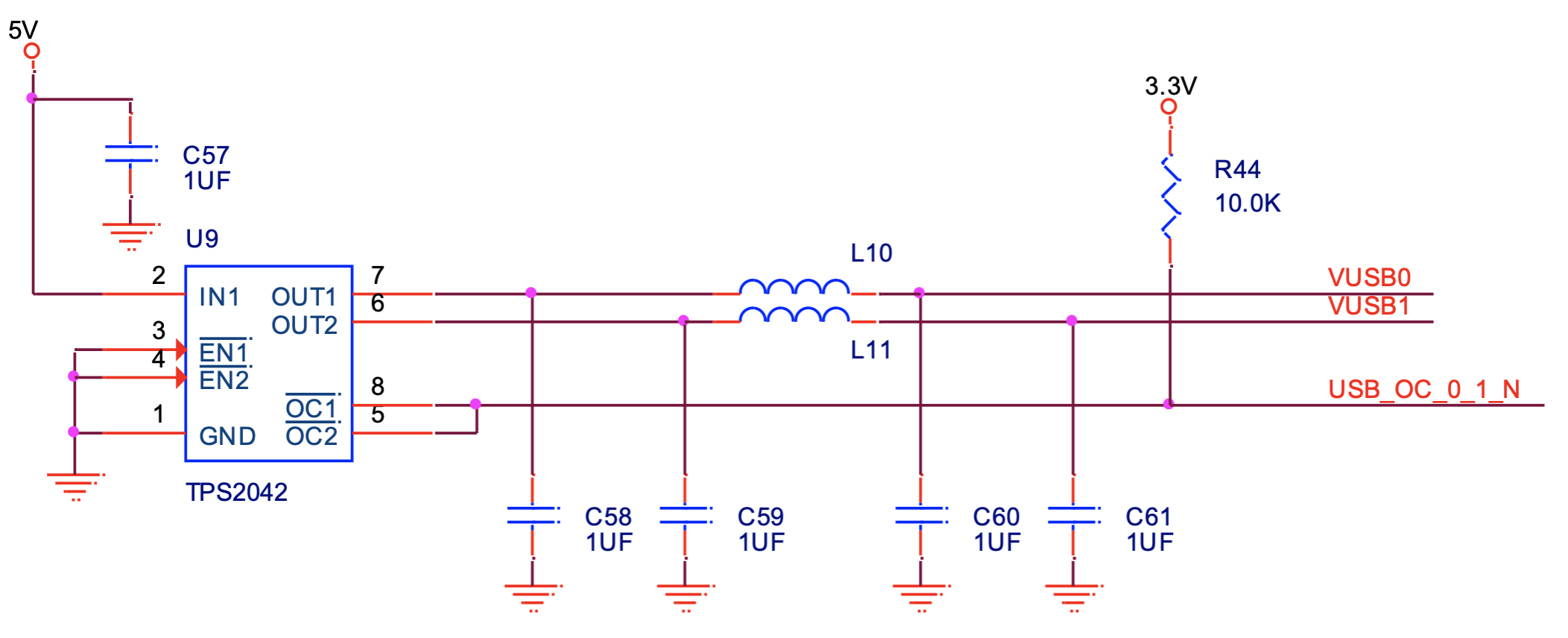
The power to each USB connector is created using a TPS2042 power switch which is always on. The TPS2042 supports two switches and current monitors. Above shows the configuration of the TPS2042 for ports 0 and 1. This is duplicated for the other port pairs. Each USB port is connected to a Type A connector and is further filtered and protected using an EMI4182 device as also shown above.
Unused Interfaces
The Piconium does not utilize the following ports on the A/B connector.
- Low Pin Count (LPC)
- SPI
- SMB
- PCI Express

